


With the rapid development of the construction industry, prefabricated buildings are increasingly valued for their advantages such as fast construction speed, controllable quality, environmental protection, and energy saving. In the construction process of prefabricated buildings, the lifting of prefabricated components is one of the key links, which is directly related to the construction efficiency and the safety of components. The reasonable arrangement of lifting points is crucial to ensure the stability of components during the lifting process and reduce structural damage. This article aims to briefly analyze the principles and methods of arranging lifting points of prefabricated components, as well as the problems and solutions that may be encountered in actual operation.
Common Lifting Systems
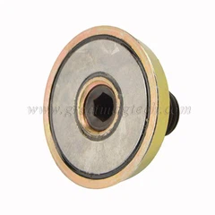
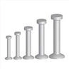
1. Lifting Anchors System
The lifting anchors system includes a lifting anchor embedded in the component and a lifting clutch. Among them, the lifting anchor is fixed to the concrete surface by a magnetic recess. The lifting load is transferred to the concrete by the circular fixed-end anchor at the other end of the lifting nail, thereby realizing quick hooking.
Features: fast lifting, suitable for conventional residential prefabricated components and industrial buildings, the maximum use load of a single lifting anchor is 32t.
Since the lifting anchor is embedded in the concrete and has end anchors, additional reinforcing steel bars are usually required to prevent damage to the concrete during the lifting process.

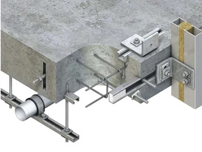
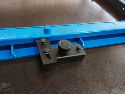
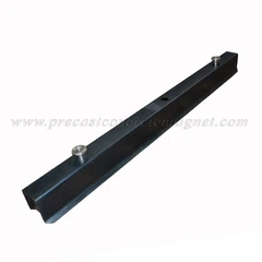
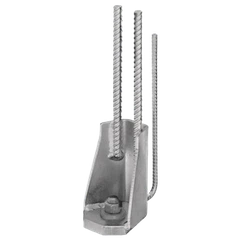
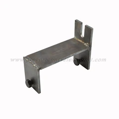
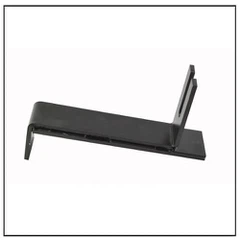
2. Erection Anchor System
The erection anchor system includes erection anchors and a ring clutch with rotating pins. Erection anchors are made of steel plates. The bottom steel plate is anchored in the concrete and fixed by a flat spherical former, and a groove is formed on the concrete surface.
The exposed steel plate is connected and fixed to the special lifting device with rotating pins in the erection anchors through the end holes. During this process, the construction personnel should rotate the pins to prevent the two from falling off. Directionality needs to be considered when arranging.
In addition to being widely used in ordinary prefabricated components, flat plate nails are very suitable for lifting wall panels of lifting systems. The end of the rotating pin of the matching lifting device can pass through the thin rope. After the component is hoisted in place, the hoisting personnel only need to pull the thin rope on the ground to unhook it, without high-altitude work, which greatly reduces safety hazards.

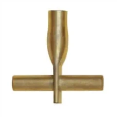
Lifting Sockets System
The lifting sockets system includes threaded lifting nails and matching external threaded lifting fixtures.
The installation and fixing of lifting sockets are relatively simple, and they can usually be directly anchored in concrete without special grooves. During lifting, construction workers can screw the externally threaded lifting fixture into the lifting nail sleeve and anchor the anchor between the thread of the component and the concrete to increase the bearing capacity.
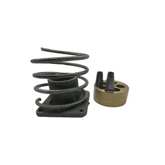
The common threaded lifting nail anchoring forms include steel bar, straight anchor, steel bar bent anchor, and steel plate, end anchor. The matching lifting fixtures include wire rope soft cable lifting fixtures and universal lifting fixtures. It should be noted that soft cable lifting fixtures cannot be used for flip lifting of components.
In addition to being applied to conventional prefabricated components, the threaded embedded lifting nail system can also cope with some thin-walled components, such as thin prefabricated wall panels and floor slabs.

Principles For The Arrangement Of Lifting Points Of Prefabricated Components
Construction personnel should also verify the position, quantity, and performance of the lifting points of prefabricated components in combination with the actual construction situation.
In addition, during the lifting of components, the staff should ensure that the hook, lifting device, and the center of gravity of the component are on a vertical line, and ensure that the horizontal angle between the sling and the component should not be less than 45°.
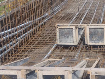
The lifting points of the composite slab should be arranged symmetrically to ensure that the composite slab is evenly stressed. At this time, construction personnel can use 4 lifting points, 6 lifting points, or 8 lifting points for lifting. It should be noted that the spacing of the lifting points perpendicular to the direction of the steel truss should be smaller than the spacing of the lifting points parallel to the direction of the steel truss so that the direction parallel to the steel truss is the main force direction to fully utilize the beneficial effect of the steel truss.
03 Arrangement Of Hanging Points Of Prefabricated Special-shaped Components
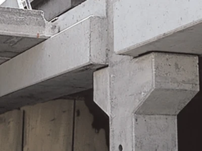
Special-shaped Prefabricated Components
Prefabricated special-shaped components refer to prefabricated concrete components with irregular shapes. Such as prefabricated bay windows, prefabricated exterior walls with bay windows, prefabricated corner exterior walls, etc.
Arrangement Of Lifting Points
Unlike regular components, the weight distribution of special-shaped components is uneven. If the lifting points are arranged conventionally during demoulding and transportation lifting, likely, the center of gravity of the component and the center of gravity of the hoist will not be on the same plumb line, resulting in tilting.
In the specific installation process, once tilting occurs, it will cause a large error in the installation of the component, which will increase the width of the joints between adjacent components, and the flatness and verticality of the component will be difficult to achieve the expected effect, which will seriously affect the accuracy of the alignment of the steel bars and the grouting sleeves at the bottom of the component.
To avoid such problems, construction personnel must scientifically arrange the embedded positions of the lifting points of special-shaped precast concrete components, clarify the center of gravity of the components, determine the lifting points, and embed the hooks, to ensure that the center of gravity of the hoist and the center of gravity of the component are on the same plumb line during the lifting process.