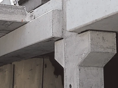


1. Precast Concrete Components
To understand precast concrete components, you must first understand precast and assembled buildings. Precast and assembled buildings refer to the construction method of buildings in which part or all of the walls, floor slabs, columns, beams, etc. are disassembled into individual independent building components and produced in a prefabricated factory. Then they are transported to the construction site by corresponding transportation methods, and these building components are assembled using reliable installation methods and installation machinery to become a functional building. These individual independent building components produced in the factory are precast concrete components. The main types are precast concrete shear internal walls, precast concrete shear external walls, composite slabs, precast columns, and beams. Among them, precast concrete shear internal walls, precast concrete shear external walls, and precast columns are all vertical components.
2. Electrical Pre-embedded Type
Different from traditional water, heating, and electricity installation. The main work of water and electricity installation of precast components produced in factories is water and electricity-related pre-embedded work. The pre-buried parts involved in the electrical part mainly include wire boxes, distribution boxes, wiring boxes, local equipotential terminal boxes, and round steel and flat iron for lightning protection.
It seems simple, but the pre-buried layout and quality directly affect the later equipment installation, wiring, single unit trial operation, and linkage trial operation.
3. Design Considerations
3.1 Single professional design
During the construction drawing stage, the electrical department can determine the electrical points according to the low area, middle area, and high area according to the needs and the later component deepening design, and consider the user needs as much as possible, design according to the fine decoration standards, and try to avoid the later water and electricity transformation.
During the component design stage, the electrical department should first be familiar with the electrical construction drawings and clarify the design requirements of each point. Take residential buildings as an example: First, we should read the design instructions and system diagrams, because the design of prefabricated components is mainly concentrated indoors, and our focus of observation is the indoor distribution lines. At the beginning of the design, we need to clarify the following points:
◇How many circuits are there in the electrical system of this project? The electrical system is divided into indoor electrical system and public area electrical system;◇How to lay the pipelines for each circuit;◇What are the requirements for the material of the pipe diameter of each circuit and how big is the pipe diameter;◇How to determine the installation height of each functional socket.◇How to deal with the lightning protection and grounding design and how to design the equalizing ring.
We need to combine the electrical plan with the component plan layout. The component plan is divided into prefabricated parts and cast-in-place parts. They also split the entire electrical system into two. At this time, our main job is to distinguish the electrical circuits, equipment, and sockets in the prefabricated part from the electrical circuits, equipment, and sockets in the cast-in-place part. Give full consideration to the connection between the two, do a good job of pipe arrangement, and take on-site docking measures so that the prefabricated components can be perfectly connected with the cast-in-place part after on-site installation to form a complete system.
After the above work is completed, the embedded framework of the electrical system basically inside the prefabricated components has been formed, and specific operation and arrangement are required at this time. The electrical system single major includes a lighting system, fire protection system, and Internet telephone system. We need to unify the various sub-projects in electrical engineering, coordinate the direction and layout of each system, and avoid and reduce collisions. For electrical points with special requirements, we must avoid them according to the regulations and also consider their practicality and aesthetics, and change the design when necessary. For example, the strong and weak point sockets installed on the wall that are most prone to collision:
The relevant specifications require that the horizontal spacing between the power socket and the weak current system information port should not be less than 150mm, and the horizontal spacing between the power cord and the socket and the TV cord and the socket should not be less than 500mm. In general electrical design, the positions of strong and weak current plugs often overlap, which requires processing.
Similarly, when making component details according to the electrical design drawings, and when determining the electrical points on the components according to the construction drawings, the horizontal positioning dimensions often "have a small tail", such as the horizontal distance from the center of the wire box to the edge of the component is 412mm, 519mm, etc. To facilitate factory pre-embedding and inspection, it can be directly rounded to 410mm or 520mm. Another thing is that electrical design should pay attention to the height of the pre-embedded electrical equipment, which generally refers to the building height rather than the structural height.
3.2 Multi-disciplinary collaborative design
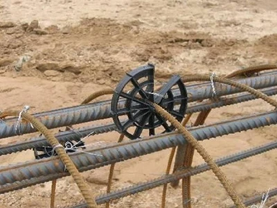
Precast concrete components are integrators of integrated designs of various disciplines and construction sections. The design of a component requires the cooperation of various disciplines such as civil engineering, structure, water supply and drainage, electrical engineering, and HVAC engineering. In layman's terms, it is how the electrical pre-embedded in the component avoids the pre-embedded water supply and drainage pipes, HVAC pre-embedded, and the steel bars in the component.
The principle of avoidance for each equipment pipeline is: ◇Small pipes give way to large pipes ◇Pressure pipes give way to non-pressure pipes ◇Low-pressure pipes give way to high-pressure pipes.
For structural steel bars, for non-fine decoration projects, the positioning of the sockets can be slightly adjusted. If the collision is more serious, it should be timely connected with the structural professionals, and the two parties should coordinate to solve it.
At the same time, it also needs to take into account the gas and floor heating that will enter the site later, because these two professions often lag seriously behind the deepening stage of the component. For example, for gas, the specification requires that the safe distance between the gas pipeline and the electrical switch socket is ≥30cm. Before the gas enters the site, the location of the gas pipeline should be estimated and avoidance should be done in advance.
4. Installation Requirements And Precautions
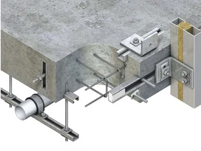
During the component production process, the main work of electrical pre-embedded is the pre-embedded socket box and the laying of wire pipes.
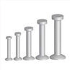
4.1 Pre-embedded wire box
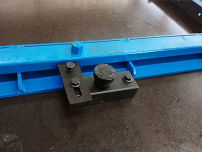
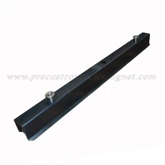
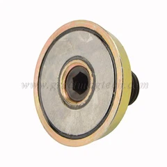
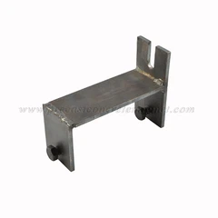
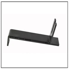
electrical insert magnets: The fixing method generally adopts wire tube fixtures, as shown in the figure below:

The size of our actual wire box is generally smaller than the panel size. When pre-embedded and positioned for parallel wire boxes, it is necessary to consider the later on-site installation. Sufficient gaps must be left between the pre-embedded positioning parts, otherwise the on-site panel will not be installed.
Wire box protection: Since the wire box needs to be poured and vibrated after being pre-embedded, to prevent the inside of the wire box from being contaminated, the outlet holes around the wire box that do not need to be connected to the pipe must be sealed tightly with tape or other methods.
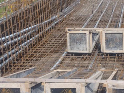
4.2 Wire pipe laying
Turning requirements: When pre-embedded wire pipes, it should be noted that the turning angle of the wire pipe pre-embedded in the wall shall not be less than 90°, the number of wire pipe turns between wire boxes shall not exceed 2, and S-bends shall not appear. The turning radius shall not be less than the minimum allowable bending radius of the cable passed through, and shall not be less than 6 times the radius of the pipe.
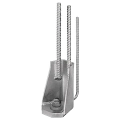
Fixed requirements: The wire pipe and the wire box are directly connected with special accessories, and the connection must be firm. The wire tube is fixed to the surrounding steel bars with wire or other materials 15cm away from the junction box. It is recommended to fix the straight section every 50cm, and both ends of the bend need to be fixed.
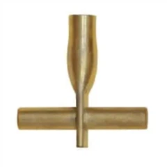
Wire tube interface reservation: The wire tube inside the component needs to reserve an interface to connect with the external electrical circuit in series. Generally, the component will reserve an operation hole at the outlet of the wire tube. The size of the operation hole should be convenient for the on-site workers to take over the space required. The wire tube should extend into the operation hole 2.5~5cm.
Avoidance requirements: The wire tube often conflicts with the steel bars around the junction box. Sometimes it is found that the outlet hole designed according to the drawing is just blocked by steel bars and cannot be connected at all. At this time, we need to avoid the steel bar connection according to the actual situation and make full use of the outlet holes on the other three sides of the junction box and the outlet holes on the back to avoid cutting the steel bars as much as possible.
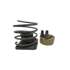
4.3 Other pre-embedding
The pre-embedding of local equipotential and weak current boxes and strong current boxes is similar to the junction box. It should be noted that the local equipotential and weak current boxes need to introduce power nearby. Deepening designers often ignore this detail, which needs to be paid attention to in factory production. If found, it should be raised during the drawing review stage.
5. Quality Control
The technical standards for prefabricated concrete buildings require that the horizontal and vertical centerline deviations of embedded pipes, wire boxes, and wire pipes on the mold should not exceed 2mm; there are specific requirements for the horizontal and vertical deviations of wire boxes on horizontal components in the component molding, but the vertical components are not clear.
The technical regulations for prefabricated concrete structures require that the centerline deviation of embedded parts on the mold should not exceed 3mm, the horizontal centerline deviation on the component molding should not exceed 20mm, and the height difference with the concrete on the surface of the component should be 0~-10mm.
The traditional industry specifications require that the height difference between wire boxes with the same specifications and elevation in the same room should not be greater than 5mm, and the height difference between wire boxes of the same model installed in parallel should not be greater than 1mm.
In summary, it can be seen that the specifications in the electrical installation industry are higher than the technical requirements of prefabricated buildings, so design and production units should not only be familiar with the specification drawings of prefabricated buildings but also understand the professional specifications and technical requirements of traditional buildings.