


(1) Vertical components should be hoisted in a slow-lift, fast-lift, and slow-release manner.
(2) A 20mm gap should be maintained between the bottom of the vertical component and the floor to ensure the flow of the grouting material; the gap should use shims of different thicknesses of 1 to 10 mm to ensure that the vertical components meet the design elevation after installation.
(3) Before hoisting the vertical components, check whether the lifting rings in the embedded components are intact, the specifications, models, and positions are correct, and the components should not be more than 0.5m above the ground during trial hoisting. The hoisting speed should be increased step by step, and the over-shift operation should not be performed. When the component is hoisted and lowered, the cable wind rope should be tied at the root of the component to control the rotation of the component to ensure that the component is stable in place.
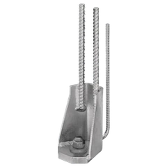
(4) When the component is about 1.5m away from the installation surface, it should be adjusted slowly to the installation position; the reserved dowels on the floor and the reserved grouting pipes of the component should correspond one by one. After all are accurately inserted into the grouting pipes, the component is slowly lowered; when the component is about 30cm away from the floor, the installer assists in gently pushing the component or uses a crowbar to perform preliminary positioning according to the positioning line.
(5) When the vertical component is in place, the vertical component should be basically in place according to the axis, component edge line, and measurement control line, and then the vertical component floor surface should be temporarily fixed by bolts and nuts using the upper and lower connecting plates of the adjustable inclined support. After the vertical component and the floor are basically vertical, the hook should be removed.
(6) According to the vertical component plane division diagram and hoisting diagram, the vertical components are hoisted into place in sequence. After the vertical components are in place, the inclined support should be installed immediately. Each vertical component is fixed with no less than 2 inclined supports. The inclined supports are installed on the same side of the vertical component. The horizontal angle between the inclined support and the floor should not be less than 60°.
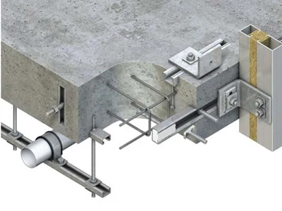
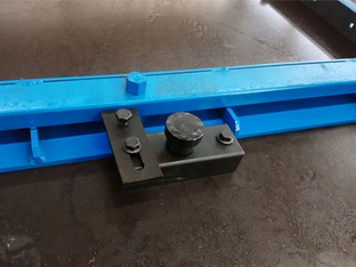
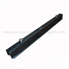
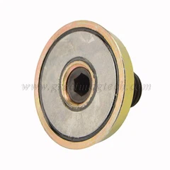
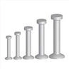
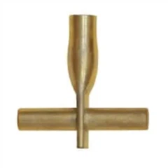
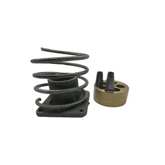
(7) Clean the pre-buried tension bolts on the ground, remove the plastic film wrapped on the surface and the splashed cement slurry, etc., to expose the connection thread; clean the sleeve on the component and install the screw. Be careful not to screw the screw to the bottom, and the gap between the screw and the component surface is about 30mm.
Prefabricated Composite Beam Hoisting
(1) Check the number, direction, appearance, specification, quantity, position, and secondary beam opening position of the prefabricated composite beam, select the steel beam shoulder pole for lifting, and the sling must correspond to the lifting ring on the prefabricated composite beam.
(2) Before lifting the prefabricated composite beam, the bottom elevation of the beam and the control line of the beam edge are marked on the calibrated wall with a black ink line.
(3) Lift the main beam first and then the secondary beam; the main beam must be calibrated before lifting the secondary beam.
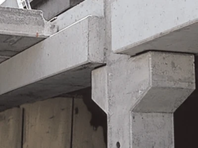
(4) The shelving length of the prefabricated composite beam is 15mm, and 1~10mm shims are used at the shelving point. When the prefabricated composite beam is in place, its axis control is placed in place according to the control line at one time; at the same time, the bottom elevation of the beam is adjusted through the lower independent support. After the axis and elevation are correct, the main reinforcement of the prefabricated composite beam is spot welded to the shear wall or beam reinforcement, and the sling is finally removed.
(5) A prefabricated composite beam requires at least two or more independent supports according to the span size. The main beam bottom formwork and independent support are put in place at the junction of the main and secondary composite beams at one time.
Prefabricated Composite Panel Hoisting

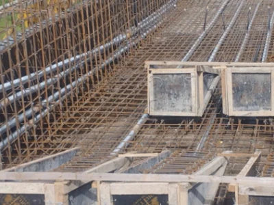
(1) Check the number of the composite board, the location and number of the reserved holes and junction boxes, and the pointer direction of the composite board. The composite board components should be hoisted in a slow, fast and slow manner. (2) The lifting points of the composite board components must be marked on the design conversion diagram to maintain the lifting balance. There must be no less than 4 lifting points, and multi-point lifting with a steel shoulder beam should be used.
(3) Before hoisting the composite board, use the ink fountain line to pop out the elevation control line on the corrected wall, and check the support elevation of the horizontal component. Cut, chisel or repair the deviation to meet the component installation requirements.
(4) Hoist the composite board components in order, and the length of the composite board should be 15mm.
(5) Install temporary supports when the composite board components are hoisted in place. The upper and lower temporary supports should be in the same position.
(6) When hoisting, the horizontal component should be lifted about 500mm off the ground first, and the slings should be checked for twisting or jamming and for uniform force on each lifting point. When the composite plate component is close to 1000mm in the installation position, hold the component steady by hand and slowly lower it into place.
Prefabricated Staircase Hoisting

(1) Before hoisting the prefabricated staircase components, check the staircase rest platform, beam mouth, and its elevation.
(2) Before hoisting the prefabricated staircase components, check the position of the embedded sleeve screws, the integrity of the thread, the weight of each piece, the number, etc.
(3) Tighten the eye screws and the embedded sleeves, adjust the length of the rigging chain, make the staircase rest platform in a horizontal position, and test hoist the prefabricated staircase board to check whether the lifting point position is accurate and whether the sling force is uniform; the test lifting height does not exceed 1m.
(4) Ensure that the prefabricated staircase rest platform is kept horizontal during the lifting process; use an adjustable horizontal lifting beam to lift it into place evenly, and the lifting points must be 4 or more.
(5) When the prefabricated staircase is in place, the steel bars of one end of the staircase section should be anchored into the composite beam with a shelving length of 15mm; the steel bars at the other end extend into the rest platform and rest on the rest platform template. The shelving length must be accurate, and the components should be accurately positioned according to the control line using a crowbar, etc. The components are required to be shelved smoothly.
(6) After installation, check the stair elevation and stairwell width.
Prefabricated Balcony And Air Conditioning Panel Hoisting
(1) Before hoisting, check the component number, the location, quantity, and appearance size of the embedded lifting rings and reserved pipe holes.
(2) The elevation and position control lines have been popped out at the corresponding positions using a black line.
(3) The location and quantity of the hoisting points of the prefabricated air conditioning panels and balcony panels must be consistent with the conversion diagram when hoisting.
(4) The negative bending moment reinforcement of the prefabricated cantilever components is extended through the reserved holes one by one. After the prefabricated components are in place, supports are set underneath them. After the correction is completed, the negative bending moment reinforcement is spot welded or tied to the indoor composite slab steel bar bracket.