


1. Design Part
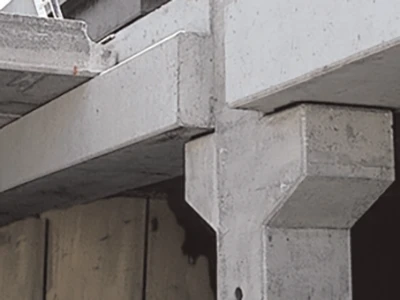
1) Slow lifting efficiency at beam-column joints, steel bar collision, unreasonable process, and frequent rework
Cause analysis
Because the steel bars are dense and the space is limited at the beam-column joints, the column main bars, column stirrups, and beam steel bars extend into the joints in four directions, causing steel bar collisions and complex steel bar layers. The unreasonable lifting sequence and process coordination cause construction chaos and low efficiency, affecting the construction period of the structure.
Corrective measures
(1) Establish the design BIM of the node during design, and solve the steel bar collision problem if it is found, such as the collision of the main bars of the beams in four directions and the collision of the main bars of the beams and the main bars of the columns.
(2) Establish the construction BIM of the node during construction, check the steel bar collision problem, arrange the process reasonably, reasonably interleave and coordinate the processes, reasonably perform the layers, and demonstrate the lifting sequence of the node according to the reasonable process to improve construction efficiency and reduce construction period waste.
(3) Lift the composite beam according to the layered flow chart.
According to the BIM demonstration, a hierarchical flow chart of beam-column nodes and primary and secondary beam nodes was established, and the composite beam was hoisted and the column stirrups were tied in the order of the flow chart.
 |
 |
2) Surface cracks of prefabricated components
Cause analysis:
(1) At the door and window openings and other locations, the reinforcement ribs were not set according to the specifications in the design drawings.
(2) Reinforcement was not performed according to the design before lifting and transportation
Corrective measures:
(1) At the door and window openings and other locations, reinforcement ribs were set according to the specifications
(2) Before lifting and transportation, the components must be reinforced according to the design requirements, and they can only be lifted and transported after passing the inspection
3) Lack of structural tongue and groove
Cause analysis
Part of the wall panels of the exterior wall components were not turned up 600 as designed, and no water-stopping tongue and groove were left, which led to leakage in the exterior wall. The horizontal joints of the components were designed to be 20mm, and the joints between the insulation boards were directly filled with cement mortar. Without water-stopping measures, they became indirect water tanks in the exterior wall layer, which directly led to leakage.
Corrective measures
(1) The design department is strictly designed by the specifications. Take waterproof structural measures at the joints.
(2) Carry out the first sample inspection of the design drawing.
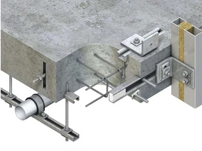
4) The three-layer stacking height of the pipeline on the composite board exceeds the height of the post-casting layer
Cause analysis
The project did not do design BIM in the design stage, nor did it do construction BIM in the construction stage. No collision check was performed on the electromechanical pipelines and steel bars, so this problem occurred
Corrective measures
(1) Complete design BIM in the design stage and perform various collision checks, including steel bars and electromechanical pipelines; complete construction BIM in the construction stage and perform various collision checks.
(2) The electromechanical and electrical boxes can be pre-buried in the prefabricated composite board, and the pipeline material can be changed to PVC material. The number of pipeline stacking layers at each location shall not exceed 2 layers.
2. Factory Production Part
1) Pre-embedded position deviation and displacement
Cause analysis
(1) The wire box is not fixed firmly, and the wire box shifts during concrete pouring or vibration
(2) The concrete vibration touches the wire box
Corrective measures
(1) The bottom of the pre-embedded wire box on the upper surface of the prefabricated component must be supported
(2) When vibrating concrete, it is strictly forbidden to touch the pre-embedded wire box and wire tube
(3) The center line position deviation of the pre-embedded wire tube and electrical box on the component plane is 20mm, and the height difference is 0~10mm.

2) Porosity and roughness on the surface of prefabricated components
Cause analysis
(1) The use of grease-based release agents leads to the formation of pores in grease-rich areas after concrete pouring
(2) The mold base is not cleaned properly. After the release agent is applied, convex areas are easily formed on the mold base surface. After the concrete is poured and hardened, pores are easily formed
(3) The concrete is not vibrated densely
Corrective measures
(1) Use water-based or oil-based release agents instead of grease;
(2) Before applying the release agent, the mold base must be cleaned, and a springboard is used for the steel bar binding and pre-embedding process. Walking on the mold base coated with release agent is not allowed;
(3) The workers are given technical instructions on concrete vibration and the vibration process is supervised for one week.
3) Omission of prefabricated component pipelines and discrepancies with on-site reservations
It was found on-site that some prefabricated component embedded pipes were missing or offset, which caused problems such as the need to cut grooves in prefabricated components during on-site installation, which easily damaged the prefabricated components.
Cause analysis
(1) Omission of embedded pipes during component processing;
(2) Pipeline installation was not carried out according to the drawings.
Corrective measures
After the components are deepened, the drawings are reviewed and handed over, and the design, construction, and production parties confirm.
To strengthen factory quality management, embedded pipelines must be constructed according to the drawings, and no omissions are allowed. Strengthen inspections before pouring concrete. Set up factory on-site representatives to understand the production status of components.
4) Main reinforcement is not inside the stirrups
The problem of the main reinforcement of the wall at the node not being inside the stirrups poses a hidden danger to the safety of the structure.
Cause analysis
(1) The main reinforcement is offset;
(2) The prefabrication plant reserves insufficient stirrup length.
Corrective measures
(1) Take corresponding remedial measures;
(2) Strengthen on-site construction management to avoid the occurrence of steel bar offset;
(3) Feedback on the information to the processing plant promptly and redesign the stirrup extension length to avoid similar problems from happening again.
3. Assembly construction part
1) Inspection and stacking of prefabricated components on-site
Prefabricated components are randomly stacked on site, and the upper and lower rows of wooden blocks are not in a straight line, which is very easy to cause cracks
Correction measures
When prefabricated components are stacked, first, the stacking site must be relatively flat. If the site is uneven, the pads need to be adjusted to ensure that the bottom pads are on the same plane, and the bottom prefabricated components are placed flat and evenly stressed; second, the number of layers of composite panels should not exceed 5; third, there must be pads between the panels, and the vertical pads must be in a straight line, and all pads must meet the requirements of the specifications.

2) Unreasonable design of the lifting point position
During the on-site lifting process, obvious cracks were generated and the prefabricated components were damaged.
Cause analysis
(1) The design of the prefabricated component itself was unreasonable;
(2) The lifting point design was unreasonable.
Corrective measures
(1) Analyze and calculate the lifting point position when designing the component to ensure the safety of lifting and the rationality of the lifting point;
(2) Return the components with missing lifting points or unreasonable lifting point designs to the factory for processing.
3) Prefabricated wall panel hoisting deviation
The deviation of prefabricated walls is a serious problem, which seriously affects the quality of the project.
Cause analysis
(1) The control line was not strictly followed during the wall installation, resulting in the deviation of the wall after it was placed;
(2) There are certain quality problems with the components themselves, and the thickness is inconsistent.
Corrective measures
(1) Do a good job of positioning and setting out the lines, and correct the wall position
(2) The construction unit strengthens on-site construction management to avoid similar problems
(3) The supervision unit strengthens on-site inspection and supervision
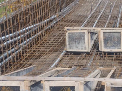
4) The protruding steel bars collided with the horizontal steel bars of the beam and wall during the hoisting of the composite slab
Cause analysis
During the hoisting and installation process, the protruding steel bars of the composite slab collided with the upper main bars of the beam and the horizontal bars of the wall, causing the displacement of the beam and wall bars and local damage to the concrete of the composite slab.
Corrective measures
(1) Establish construction BIM during design to find the problem of steel bar collision and the solution, such as the beam stirrups can be designed as open stirrups, and the upper main bars of the beam can be tied and installed later.
(2) Establish construction BIM during construction to demonstrate reasonable procedures, determine the layered construction sequence and correct construction procedures, and reflect the construction characteristics of prefabricated buildings. For example, the steel bars of the beam are tied after the composite slab is hoisted, and the upper horizontal bars of the wall are tied after the composite slab is hoisted.
5) Prefabricated components are not densely grouted
Cause analysis
(1) Irrational grouting material configuration;
(2) Sleeve drying;
(3) Grouting pipes are not smooth and joints are not dense, resulting in leakage;
(4) Operators are careless and fail to fill the grouting, and garbage is not cleaned up.
Corrective measures
(1) Strictly follow the proportion and material discharge sequence in the instructions for preparation, and control the mixing method and mixing time according to the instructions;
(2) Before hoisting the components, carefully check whether the grouting pipes and joints are unobstructed. A small amount of water can be appropriately sprinkled on the grouting holes half an hour before grouting to moisten them, but no water should accumulate;
(3) When using a pressure grouting machine, the grouting holes in a component should be filled continuously at one time, and the surface of the grouting holes should be compacted and smoothed before the grouting material is finally set;
(4) After the grouting material is mixed, ensure that the material is used up within 30 minutes;
(5) Strengthen operator training and management to improve construction personnel's awareness of construction quality.
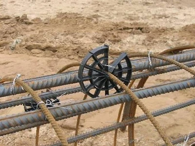
6) Displacement of reinforcement bars in prefabricated components
Cause analysis
(1) The vertical reinforcement bars were not limited and fixed before pouring the floor concrete;
(2) The pouring and vibration of the floor concrete caused the vertical reinforcement bars to shift.
Corrective measures
(1) Use reinforcement positioning fixtures to limit the position according to the component number, and use support bars to support the reinforcement frame appropriately to ensure the accurate position of the reinforcement bars;
(2) After the concrete pouring is completed, the center position of the reinforcement bars of the reserved wall column components on site shall be checked according to the reinforcement plan layout and the on-site component edge line or control line. For the reinforcement bars with a center position deviation of more than 10mm, appropriate corrections shall be made according to the drawings.
7) Steel bar connection problems
The steel bar connections at the cast-in-place nodes have problems such as sleeve joints not being tightened, lap joints being perfunctory, and steel bars being severely bent, which pose a hidden danger to structural safety.
Cause analysis
(1) Workers did not operate properly when connecting steel sleeves;
(2) On-site supervision and management were not in place.
Corrective measures
(1) Strengthen protection measures for steel sleeve joints during platform concrete pouring to avoid debris on them;
(2) Workers should take measures such as cleaning and oiling when connecting steel bars to ensure that the quality of sleeve connections meets the requirements of the specifications;
(3) Management personnel need to strengthen on-site management, and strengthen inspections of each sleeve connection, supervisors should do a good job of on-site supervision, and the engineering department should conduct a careful re-inspection and rectify problems promptly.
8) Cracks in the composite slab
Cause analysis
(1) The composite slab has not been maintained for long enough and has not yet reached the required strength;
(2) The support is not set according to the regulations, resulting in cracks in the composite slab.
Corrective measures
(1) The support position under the composite slab must be determined by calculation;
(2) The construction unit is required to replace the composite slab with a qualified one. Considering the progress on site, a special repair plan can be submitted to the supervisor and Party A for approval before rectification;
(3) The construction unit is required to strengthen on-site management. The composite slab must reach 100% of its strength before it can be dismantled and hoisted. The supervisor is required to strengthen on-site inspection and supervision.
9) Nodes are not cast in place
Cause analysis
(1) The concrete casting of the edge component reinforced cast-in-place node area is not in place, which poses a quality risk. Follow conventional treatment methods and preventive measures;
(2) The cast-in-place nodes are not dense and have dog holes, which affects the safety of the structure. Follow conventional treatment methods and preventive measures.
Corrective measures
Strictly control the slump of concrete, sand and gravel grading, concrete vibration, and maintenance work, especially focusing on tracking and supervising the concentrated areas of corrugated pipes and wire pipes (boxes).
10) Leakage at the opening
Cause analysis
Irrational setting of cantilever scaffolding, inadequate handling of the position of the wire pipe joints, leakage caused by improper setting of the cantilever scaffolding holes and screw holes, and loose plugging of the scaffolding holes and screw holes, causing leakage.
Corrective measures
The cantilever scaffolding plan at the construction site must be determined in conjunction with the design department, and the position of the cantilever scaffolding must be determined in advance. The longitudinal steel bars must be avoided during the conversion design. A special construction plan must be formulated for the plugging of the cantilever scaffolding holes, wire pipe joints, and through-wall screw holes at the construction site. They must be cleaned and moistened with water before plugging. Dry hard (concrete) cement mortar must be used for plugging, and micro-expansion agents must be added in proportion to fill the holes in layers. The plugging thickness of the cantilever scaffolding holes is the same as the wall thickness. After drying, two coats of JS cement-based paint must be applied. The quality inspector conducts special acceptance for each facade and each layer.
11) The electrical pipe is blocked
Cause analysis
Unreasonable design of buried bolts, omissions on site, and large-scale use of expansion bolts as substitutes lead to blocked electrical pipes.
Corrective measures
(1) The design department provides the construction site with the positioning diagram of the embedded bolts based on the design 3D model and the length and angle of the inclined support; at the same time, check whether it collides with the wire pipe and wire box during the construction process, and provide modification diagrams in time;
(2) The on-site quality inspector conducts inspections based on the embedded bolt positioning diagram, including: whether the position is correct and fixed, whether it is omitted, the exposed length of the thread and its protection; if it is found that it collides with the embedded wire pipe and wire box, contact the project technical person in charge or the design department in time to make modification suggestions.
12) The vertical sleeve grouting is not dense and full.
Cause analysis
The bubbles in the connecting cavity are not completely removed, the grouting material is not left for a long time, the bubbles are not completely removed, the liquid level drops after the grouting stops, resulting in the grouting being not dense, the grouting pressure is not enough, resulting in the bubbles not being completely removed, and the grouting speed is too fast.
Corrective measures
(1) A single exhaust hole at the connecting cavity between the column and the wall, which is 150mm higher than the grouting hole of the steel sleeve, is set to ensure that there is slurry replenishment when the grouting material in the sleeve is returned;
(2) After the grouting material is stirred evenly, it should be left to stand for about 2-3 minutes to allow the bubbles in the slurry to be naturally discharged before use;
(3) The connecting cavity must be tightly sealed on all sides, and the pressure should be maintained for 30 seconds after all the grouting and drainage holes are blocked.
13) Remedial measures for the failure of grouting to flow out of individual joints of sleeve grouting or the grouting to be dense
Cause analysis
The connecting cavity is not tightly closed or the bubbles in the connecting cavity and grouting material are not completely removed.
Corrective measures
(1) Within 30 minutes of mixing the grouting material with water, open all blocked holes and refill the grouting holes;
(2) When the grouting material mixture has stopped flowing, drill holes in the grouting holes for refilling. This should be combined with capillary pressure grouting: use a plastic bottle and a plastic hose with a diameter of 8mm to refill the grouting through the sleeve grouting hole (drilling hole 12mm). The hose should be extended to the innermost end of the hole. As the grouting material flows out, slowly pull out the hose to remove the air.